A Preliminary Analysis of the Impact of Stator Slot Fill Factor in Wound‑Wire Motors on Manufacturing Processes


As new‑energy vehicle technology continues to advance, customers are placing increasingly stringent demands on motor power density—defined as power per unit weight. Under the same weight constraints, how can we achieve higher power output?

One very important approach is to increase the stator slot fill factor. What is it? Slot fill factor ?

That is, within the core slot Conductor cross-sectional area and Total area of the core slots The ratio— the higher the motor slot fill factor, the more it indicates… “The copper wire is packed more tightly into the iron core slots.”


Schematic Diagram Comparing Slot Fill Ratios

As can be seen from the above figure, Flat-wire motor Due to Slot fill factor Its significant improvement has made it the clear mainstream for new‑energy drive motors. From a product perspective, of course… The higher the slot fill factor, the better. However, on the other hand, the continuous increase in slot fill factor poses significant challenges to the manufacturing processes and the precision and complexity of the equipment used for flat-wire motors.

So, where exactly lies the challenge in increasing slot fill factor when manufacturing flat-wire stators?

First, high precision and consistency are required in the forming of copper wires. During the forming of copper conductors, it is impossible to achieve perfect conformity with the theoretical 3D CAD model; deviations and fluctuations in profile accuracy, straightness, and other parameters are inevitable. Consequently, compared with the 3D CAD model, a bundle of copper conductors within the slot does not align as neatly during insertion. This lack of uniformity significantly increases frictional resistance when the conductors are pressed into the core slots, requiring greater insertion force to overcome it. However, excessive insertion force can lead to issues such as incomplete seating, conductor extrusion or damage, and slippage of the insulation paper. The higher the slot fill factor, the smaller the design‑specified clearance within the core slots, and the lower the tolerance for such irregularities.

The key to wire forming lies in controlling the dimensional accuracy of the hairpin. Because copper wire exhibits a certain degree of springback during forming, the 3D mold geometry cannot be simply derived from the wire’s CAD model; instead, several factors that influence the amount of springback must be taken into account:

  • Wire specifications — copper wire width and thickness
  • Hairpin shape—span, curvature, angle, etc.
  • Elastic modulus of the substrate—mechanical properties inherent to copper itself
  • Coating material—both the thickness and composition of the coating also affect copper.
  • It affects the overall elastic modulus of the wire.

When designing molds, Yueke analyzes and simulates the copper wire forming process based on the aforementioned factors, and, drawing on extensive practical experience, develops the most optimized mold contour to achieve the highest dimensional accuracy. The overall contour accuracy of the wire profile can reach 0.1–0.2 mm.

In addition, during the online forming process, visual inspection can be used to perform 100% in-line dimensional verification of the formed copper wires, thereby preventing defective wire configurations caused by anomalies from advancing to subsequent stages.

Secondly, all alignment- and guidance-related mechanisms and components of the equipment must meet stringent precision requirements. When inserting the hairpin into the core, all slots (48, 54, 72, etc.) must be precisely aligned with the core’s slot openings to ensure smooth insertion of the copper wire. The higher the slot fill factor, the greater the precision required for alignment.

During the wire‑insertion process, it is essential to ensure precise alignment of the axes and angles of the entire sequence of mechanisms, including the wire‑holding assembly, the inlet guide mechanism, the stator core, and the core‑positioning base. Typically, axial alignment accuracy should be maintained within 0.05 mm, and angular alignment accuracy within 0.02°.

It places significant demands on automation suppliers’ capabilities in mechanical design, machining, assembly and commissioning, as well as electrical control.

Furthermore, the risk of slippage of the insulating paper during wire entry increases. A high slot‑fill factor increases the friction between the copper conductor and the insulating paper during wire insertion, making the insulating paper prone to axial slippage driven by this friction. Therefore, it is essential to maximize the wrapping dimensions of the insulating paper while providing adequate support beneath it during wire insertion and crimping.

Increasing the envelope dimensions of the insulating paper means that, during insertion, the paper will conform more tightly to the inner wall of the iron core, and the frictional resistance when the paper exits the core slots will rise, significantly elevating the risk of edge curling and deformation during insertion.

In particular, for oil‑cooled motors, the insulating paper typically lacks a polyimide interlayer, resulting in lower mechanical strength and greater susceptibility to deformation under stress during the paper‑insertion process, which further complicates automated insertion.

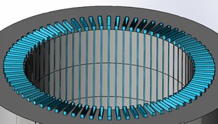
Finally, filling with dripping paint is even more challenging. During the impregnation process, the varnish primarily infiltrates the slots via capillary action. As the slot‑filling ratio increases, the voids within the core slots become smaller. Although, in theory, the capillary penetration of the impregnating varnish should improve, the reduction in void size can easily lead to localized blockages caused by turbulence or microgel formation, preventing effective venting of air from the slots and ultimately resulting in a decline in the filling rate.

The figure below illustrates the variation of capillary penetration and venting performance as a function of the gap size within the groove. Under the combined influence of these two factors, achieving optimal impregnation and filling requires setting the groove gap near the intersection point of the curves.

The stator, designed through optimization, employs an inclined dip-coating process, enabling Yueke to achieve a dip-coating fill rate of 90–95% at present.

Therefore, the design of the motor slot fill factor should be determined from a holistic value‑stream perspective, balancing product performance requirements, process and equipment capabilities, production‑line stability, and yield to arrive at the most optimal setting. So, how should the slot fill factor typically be specified during motor design?

From a manufacturing perspective, the primary focus is on the “mechanical slot fill factor” rather than the “pure copper slot fill factor,” taking into account both the insulating paper and the varnish film. Typically, this is evaluated in two directions: radially and circumferentially.

Radial clearance = Core slot depth − (copper wire thickness × number of conductors per slot + insulation paper thickness × 3) ≈ 0.5–1.0 mm

Circumferential clearance = Core slot width − (copper wire width × 1 + insulation paper thickness × 2) ≈ 0.1–0.2 mm

The final value must be determined by comprehensively considering factors such as the number of copper wire layers, the stack height of the iron core, the number of slots, and the specifications of the copper wire.

Yueke Intelligent Manufacturing (Wuxi) Co., Ltd. boasts extensive experience in process application and robust capabilities in equipment design and manufacturing. It collaborates with customers from both product‑ and process‑perspectives to identify the optimal solution for manufacturability, while leveraging highly precise, high‑efficiency equipment to produce stators with higher slot fill factors—continuously meeting end‑users’ relentless pursuit of superior performance in new‑energy vehicle drive motors.